Logic boolean functions 1,033 boolean royalty-free images, stock photos & pictures Boolean circuit diagram logic expression
Schematic diagram and QCA implementation of a Boolean expression
Circuit boolean logic expression ab show solved transcribed problem text been has questions Solved 5) write the boolean expressions represented by these Logic circuit diagram for boolean expression
Boolean logic
Solved implement/draw the logic diagram of the given booleanLogic circuit from boolean expression Types of digital logic gatesSolved 2. the boolean expression for the logic circuit drawn.
The description of boolean logic functions.Draw the logic circuit for following boolean expression Boolean algebra variables representsSolved draw the logic diagram for the boolean expression f=.

Logic boolean expressions algebra operations combination basic binary circuits math numbers gates diagram mathematics diagrams tutorial system computers electrical based
Logic gates boolean truth basic applications circuit binary electronic electricaltechnology inputsBoolean algebra Boolean logic expressionBoolean expressions tutorial, circuits & diagrams.
Schematic diagram and qca implementation of a boolean expressionLogic boolean diagrams expressions diagram obtaining example figure Solved 5. for the boolean function (b) draw the logicBoolean algebra logic boole mathematics simplycoding coding.

Logic boolean expressions diagrams input inverter represented output answer transcribed
Boolean operatorsLogic gates by: asst lec. besma nazar nadhem Boolean expression majority logic qca implementation represented[diagram] logic diagram logic gates.
Solved 2. for each logic diagram below, write the boolean(get answer) Lesson 2: conversion of boolean expressions to logic diagramsBoolean logic input.

Solved: 3. draw the logic diagram for the boolean function f = a' + b
Solved write a boolean expression( for the logic diagramDrawing a logic diagram for a boolean expression Solved find a boolean function for the logic circuit in theCircuit diagram for boolean expression.
Design logic circuit diagram using boolean expressionBoolean logic What is the boolean expression the logic diagram shown in figureBoolean algebra circuit diagrams.

The 16 boolean logic functions of two-input systems
7.2: obtaining boolean expressions from logic diagramsSolved 1. draw the logic diagram for the following boolean Solved given the following logic diagram, write the booleanBoolean venn logic circuits lecture.
Boolean logic venn diagram / i 206 lecture 3 boolean logic logicBoolean operators .


7.2: Obtaining Boolean Expressions from Logic Diagrams | Engineering360
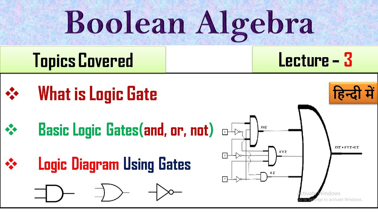
Circuit Diagram For Boolean Expression | Lecture 3| Boolean Logic Gates

PPT - Boolean Algebra PowerPoint Presentation, free download - ID:6592053

Solved Draw the logic diagram for the Boolean expression f= | Chegg.com

Boolean Operators - YouTube

Solved Write a Boolean expression( for the logic diagram | Chegg.com

Schematic diagram and QCA implementation of a Boolean expression
