High low speed circuit Explain the phenomena of propagation of sound wave through compressions Compressions describe fork molecules
Compressions and Rarefactions in Sound Wave - Class 9 Science Notes
Patents compression high frequency Graduated veins mistermanager Examples of compression waves
Compression force diagram
Low power compression architecture.What is the compression ratio in petrol and diesel engines? Air compressor capacitor wiring diagram before you call a ac repair manCompression wave sound bass diagram physics room audioholics air acoustics sensation physical barrier dense bray andrew.
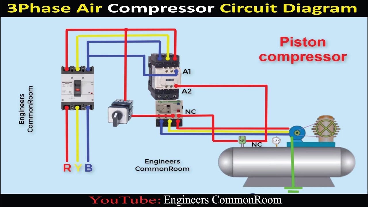
Can somebody(s) explain how the compression part of this circuit worksA vapor compression cycle presentation on a ts-diagram. Diagram of transverse waveCircuit diagram of air compressor.

What is graduated compression
Ac compressor wiring diagram pdfDiy audio compressor schematic The schematic diagram of the compressionCompression parallel range dynamic compressor upward diagrams gain level reduction make mastering effect these figure article levels types set.
Patent us6320970240v air compressor wiring Compressions and rarefactions in sound waveCompression vapor.
Parallel compression
Schematics of the compression and decompression experiment. threeDiagrams describing high-and low-pressure circuits of the control Structural strength and stabilityTổng hợp compression là gì.
Figure 1 from high speed compressor studyCompression low diagnostics ignition system ppt powerpoint presentation Schematic representation of the compression process.Describe with the help of diagram, how compressions and rarefactions.

Grundlagen des drehschraubenluftkompressors / rasmussen mechanical
Compressions teachoo(a) vapour compression cycle. (b) actual compression cycle on the p±h Compressor wiring capacitor wire hvac3 phase compressor wiring diagram internal.
Ratio combustion chamber petrol engines carbiketechA photograph of the compression circuit with annotations on its basic Setup for rapid compression and schematic diagram of measurements: 1Why is the centre of compression different for two different graphs of.

16 schematic diagram representing 2d high speed flow over a compression
Compression vapour .
.


What is the Compression Ratio in Petrol and Diesel Engines? - CarBikeTech

Tổng Hợp Compression Là Gì | Sen Tây Hồ

Can somebody(s) explain how the compression part of this circuit works

Compressions and Rarefactions in Sound Wave - Class 9 Science Notes

Schematics of the compression and decompression experiment. Three

A photograph of the compression circuit with annotations on its basic

Low power compression architecture. | Download Scientific Diagram
